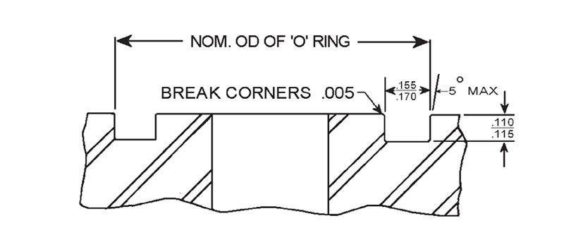
Sae code 61 o ring groove dimensions SAE Flange are designed to conform to Oring groove, bolt holes and bolt pattern dimensions of either Code 61 of SAE J518 and ISO (Code 61) a Annular (circumferential) tool marks up to a surface roughness value of ISO 1302MRR Ramax 3,2 are acceptable Scratches with a width greater thanTable 50 Type R ring gaskets (see Annex B for US Customary units) a) Octagonal b) Oval c) Groove Dimensions in rnillimetres Ring number R H 23 R 24 R 26 li 27 K 31 R 35 R 37 R 39 R 41 R 44 R 45 R 46 R 47 K 19 R 50 R 53 R 54 R 57 Pitch diameter of ring (groove) P 0,18 (* 013) 68,28 55 95,25 107,95 149,23ORing groove and dimensions may be calculated as follows (please refer to chart above) Given Example Given Example Rod Diameter C = 500 Cylinder Bore A = 1000 Oring Cross Section W = 3/32″ nominal Oring Cross Section W = 1/8″ nominal Dynamic Application Static application No backups required No backups required Determine Determine Oring size = AS568
Http Www Allsealsinc Com Parcoo Ringsizechart Pdf
Size chart o ring groove dimensions pdf
Size chart o ring groove dimensions pdf-From the finest precision seals to the largest heavy duty shaft seals and packings Our products address the needs of customers that wish to have a broadORing Size Guide The safe choice for seals and moulded parts used in hydraulics, pneumatics, precision engineering, food/medical industries, oil & gas, valve & pump and aerospace M Seals specialises in seals for industrial use;


Engineering
Le Joint Français 'R' metric Oring sizes;This reference table gives the dimensions of all BS Orings available right now British Standard (BS) Orings come in many styles and sizes 44 (0) 1909 560 3Be it dynamic or static operation, radial or axial loading, vacuum or high pressure The following information is a guide for o'ring groove dimensions for both static and reciprocating dynamic applications The info is based on 70 Shore A Durometer hardness only Surface Finish Generally
ORings Dimensions & Illustrations wwwPrecisionAssoccom In order to assure size accuracy, make sure that Page Scaling is set to NONE prior to printing this document Change this setting by selecting File, Print Page Handling Page Scaling None After printing, verify that size is correct by chec king scale on printed page Precision Associates, Inc Phone (612) 3800 NORING REFERENCE AS568 SIZES 1 THE FREUDENBERG–NOK SEALING TECHNOLOGIES ORING DESIGN QUICK REFERENCE This design quick reference guide is intended for use in specifying Oring and groove dimensions for static applications with pressures less than 1500 psi The guidelines are for the nominal condition The minimum and maximum conditions should also be checkedJapanese Standard JIS B 2401 (P, G and V) Oring sizes;
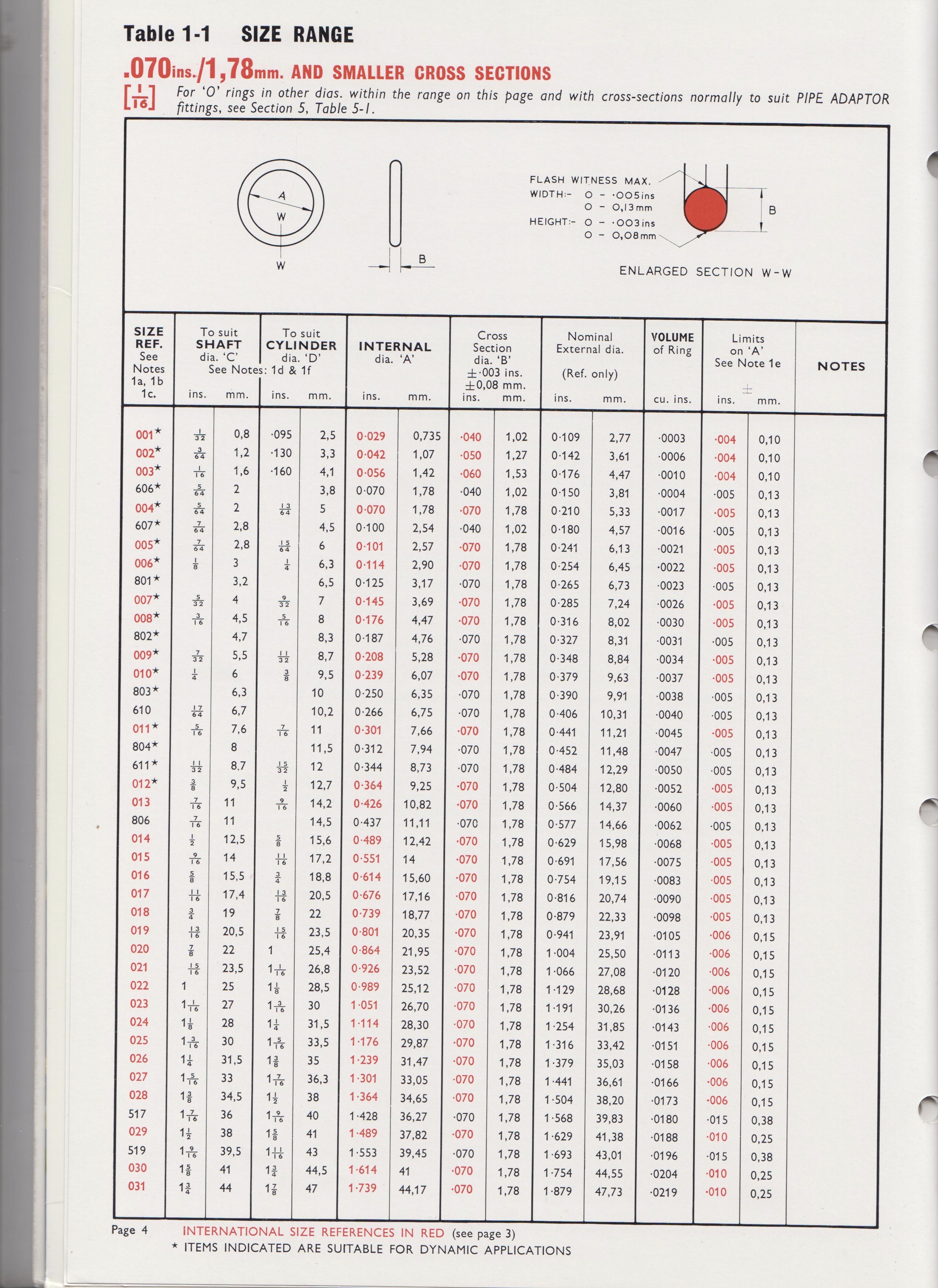
Piston Groove Ø B Gland Groove Ø D Rod Ø C INCH ± mm ± INCH ± mm ± INCH STAT DYN STAT DYN ± 003 ± 003 ± 003 Only sizes marked * are suitable for dynamic applications HQ, EXPORTS CENTRAL WAREHOUSE Reginald Road, Smethwick, West Midlands, B67 5AS Tel 44 (0)121 429 8011 Fax 44 (0)121 434 3016 sales@barnwellcouk / export@barnwellcoukStandard Oring Size 353 / 010 0139 / 0004 262 / 008 0103 / 0003 BS1806 British Standard Oring sizes (imperial) wwwperlastcom International Oring Standard Sizes PAGE 4 Millimeters Inches Internal Internal Cross Internal Internal Cross Diameter Diameter Section Diameter Diameter Section (mm) Tolerance / (mm) (inches) Tolerance / (inches) BS1806British Dowty Oring sizes;


1


Www Pressureseal Com Orings Oguide Pdf
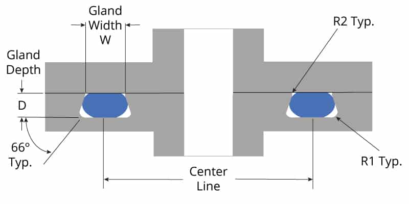
The groove must be designed to accommodate not just the o'ring size, but also its intended usage;Also provides an overview of international sizes and standards, and compatibility data for fl uids, gland design recommendation charts troubleshooting utility pressure calculator • ParZap inventory management • Worldwide distribution • Extensive product literature, test reports and much more 5 t A E II Parker Hannifi n Corporation • ORing Division 2360 Palumbo DriveDimensions of orings in one ordering number How to Determine ORing Size* For Sequence in Ordering 1 Size (catalog number) 2 Durometer and material 3 Quantity Example 110 – 70SLR – 10,000 (size – durometer, material and color – quantity) Outside diameter (OD) is for reference only ORings are specified by ID and cross section


O Ring Groove Design Standard As568b Seal Design Inc


Http Www Allsealsinc Com Parcoo Ringsizechart Pdf
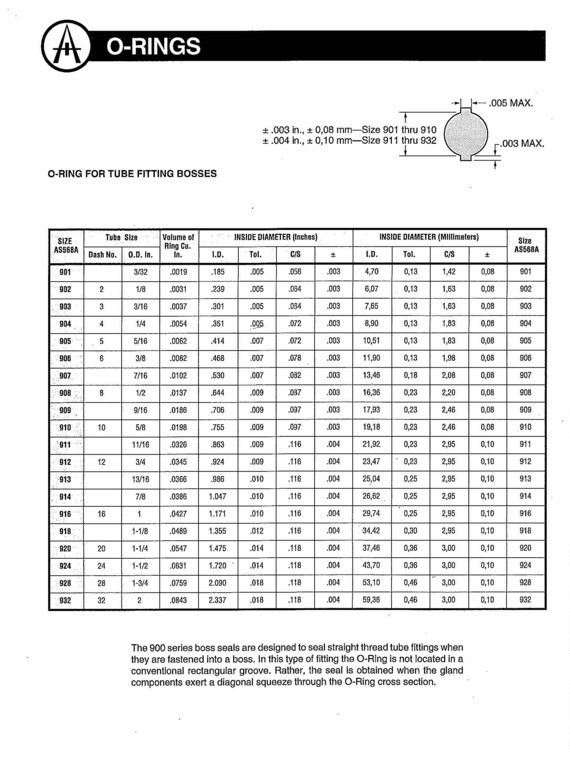
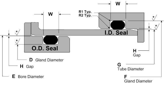
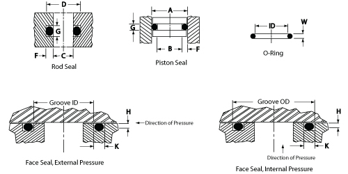
A chart listing the most popular compounds and their fluid compatibility / technical information Learn More > ORing Groove Design ORing Groove design plays an important part in how an oring seals Learn More > Contact World Class;901 3/32 902 1/8 903 3/16 904 1/4 905 5/16 906 3/8 907 7/16 908 1/2 909 9/16 910 5/8 911 11/16 912 3/4 913 13/16 914 7/8 916 1 918 11/8 9 11/4 924 11/2 928 13/4GROOVE DIMENSIONS AND MACHINING CONSIDERATIONS Example of Determining Groove Dimension Determine the appropriate groove dimensions and tolerances for the following seal Reciprocating seal, OD sealing Size 214 0Ring Solution PISTON GLAND PISTON GROOVEÐIA ROD GLAND B RODOD, MIN MAX—2 L MAX) C PISTON 00 A CYLINDER BORE DIA D ROD


Size Chart O Rings Chemistry Materials


Projects Iq Harvard Edu Files Epm Oring Handbook Pdf
Chart 50 inch & metric sizes 1316 'O' rings for pipe fittings 16 Aerospace sizes to BS ISO 17 Chart 72 metric sizes 2122 Chart inch sizes 23 Nonstandard sizes 24 Complementary products Coloured materials 25 'O' ring cord 25 Commercial quality 'O' rings 25 'O' ring kits 26 Special packaging & kits 26 'O92 Parker Hannifi n Corporation • ORing Division 2360 Palumbo Drive, Lexington, KY Phone (859) † Fax (859) wwwparkeroringscom Sizes Parker ORing Handbook SizesGroove dimensions on pages 30 and 31 to decide what is the closest size 'O' Ring, again bearing in mind the points made in section 1 3) If you are at the design stage there are a multitude of considerations, but try to keep your selection simple As far as possible choose exstock sizes and material Only specify exotic or completely nonstandards if you have no other choice Keep to


Designing Axial Static O Ring Grooves To Industry Standards Grabcad Tutorials
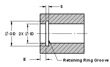


Internal Retaining Snap Ring Sizes And Groove Design Chart Engineers Edge
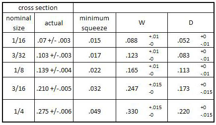
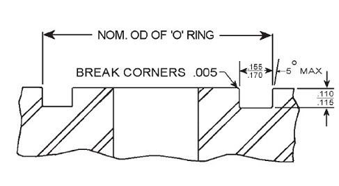
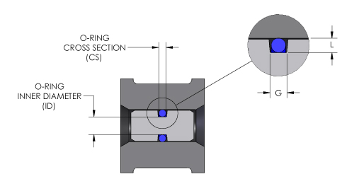
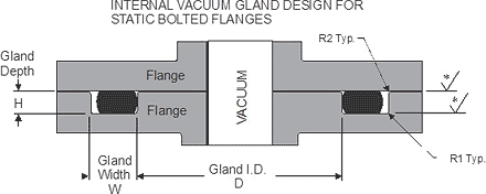
The housing dimensions for static radial sealing Orings are listed in the size lists Housing groove edges All housing groove edges should be smoothed and rounded off ( fig 1 , fig 2 ) to r = 0,1 to 0,2 mm (0004 to 0,008 in)Based on the cross section (CS) of your Oring, you will choose the corresponding Oring groove depth and Oring groove width dimensions The Oring inner diameter (ID) should also stretch approximately 5% over your groove or gland If you have a custom Oring size that does not appear on this chart, contact us directly and we can help you size your Oring gland designSecond Pick the series Oring desired, based on the thickness of the flange available to cut the groove depth desired (I244) Third Check the swell characteristics of the fluid on the rubber to determine whether the normal or high swell chart will be used for dimensions of the Oring groove (In this case 015% or normal swell Chart I)
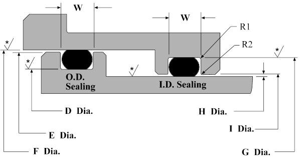


Dynamic O Ring Design Chart Marco Rubber Plastics Custom O Rings Supplier


Newdealseals Com App Uploads 04 Newdealseals O Ring Handbook 14 Pdf
Hardness All Ring SizesHRC 4252 Free Diameter & Ring Measurement with Section BB Housing Diameter & Groove Dimensions Material SAE Snap Ring, Internal, Inch Designed for needle bearings, once installed in the groove of a housing/bore, the portion of the ring protruding from the groove holds an assembly in place For the most uptodate specifications, onlineORing cross section and oring groove design data from ROW, Inc manufacturers of encapsulated orings and industrial gaskets Cross Section & Groove Design Data Helpful links Cross Section & Groove Design Installation Instructions Small ID Encapsulated ORing Ovality Available Cross Sections for Encapsulated ORings & Groove Design Data CROSS SECTIONS h Groove style B i Screw threads SAE J1453 ORFS Groove and orfs o ring sizes chart as follows Dimensions in millimetres Oring Surface B d f i 1 i 5 d 4 Tube outside diameter Thread a Outside diameter Inside diameter nom tol ± 0,4 min nom tol min max 6 9/1618 UNF 2,4 ± 0,3 10 9 7,65 ± 0,16 11,08 6,1
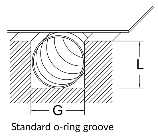


Spira Shield Spira Manufacturing


1
Visit our Oring groove dimensionGerman Standard DIN3771 metric Oring sizes replaced by ISO3601 standard;Call Us Seal & Design Canada Toronto, Ontario (416) Toll Free Headquarters Clarence,


Buna O Ring O Ring In Houston And Minneapolis Dichtomatik


Danco O Ring Size Chart Shefalitayal
Oring rolls in the groove and creates torsion, a QuadRing actual groove dimensions are needed to supply the correct sized machined backup ring Note 3 Use FKM QuadRings®/XRings with minimum stretch because FKM QuadRings®/XRings have a smaller tolerance range than NBR QuadRings®/XRings Standard cross sections of QuadRings®/XRings Application Range fromMETRIC IMPERIAL IMPERIAL BS Reference Alternative References ID Section OD ID Section OD ID OD BS 548Dimensions RingJoint Facings ASME B165 Pressure Class 150 (1) The height of the raised portion is equal to the depth of the groove dimension, E, but is not subjected to the tolerances for E Former fullface contour may be used (2) For ring joints with lapped flanges in Classes 300 and 600, ring and groove number R30 is used instead of R31


O Ring Size Chart Pdf Sae O Ring Size Chart


O Ring Groove Design Guides Engineering Quick Reference
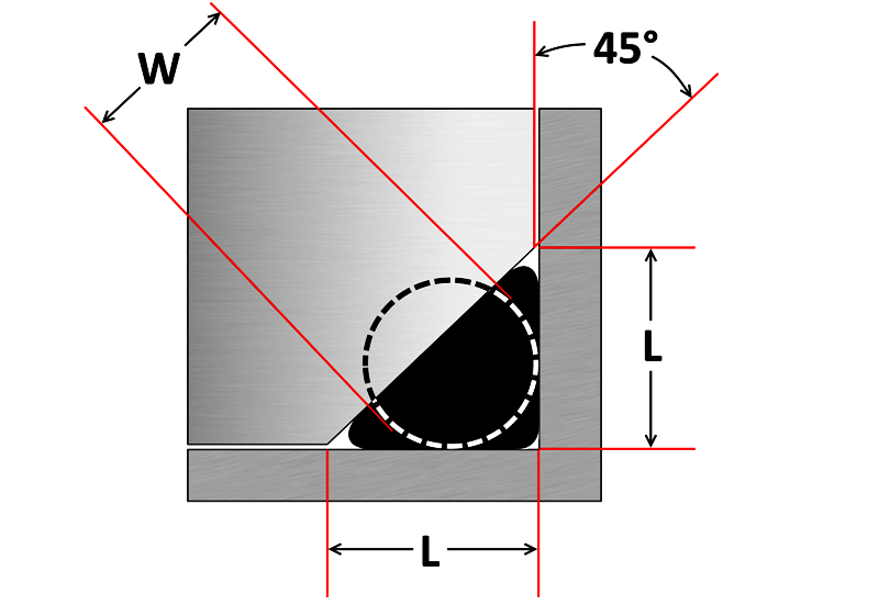
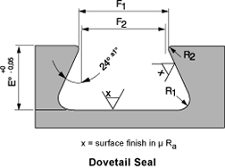
DOVETAIL ORING GROOVE DIMENSIONS Dovetail grooves are used to hold the Oring in place during installation or maintenance This groove design is relatively uncommon as it is expensive to machine and should not be used unless absolutely required The dovetail groove construction is only recommended for Orings with bigger cross sections, 1390045" for 4 – 6";MS ORING CHART SIZING (IMPERIAL SIZES) Part No marked in red are stock lines EMail sales@asapsparescomau Where Good Old Fashioned Service & Loyalty still Prevails Catalogue Index Use the chart below to determine the size All sizes are NOMINAL REFERENCE CHART ONLY Our Part No ID OD Width Our Part No ID OD Width MS 1/32 3/32 1/32 MS


O Ring Groove Design Sealing Australia


How To Calculate The Right O Ring Size With The Parker O Ring Selector
ORing Seal Sizes NOT all sizes readily available in all materials For quotes, prototypes or questions, call ORing Seal Sizes For quotes, prototypes or questions, call ORing Seal Sizes NOT all sizes readily available in all materials For quotes, prototypes or questions, call Bold type denotes Standard AS568 Please checkTechnical Handbook Orings 14 Oring Size Charts 8 hours ago Oringinfo Get All 14 Oring Size Charts Note The AS Oring Size Chart has a column that shows the Nominal Size alongside the Actual Size Originally the nominal size was just for a listing of the approximate fractional dimensions of the OringPrior to the common use of dial calipers many people called out a 1Shortly after ORings first came into common use, it became obvious that standards for ORing sizes, tolerances, and groove design would be beneficial The first standards were issued in 1942 Since then various government and engineering organizations have produced a multitude of ORing standards From this large list we chose to include the following national and international ORing


Ruander Com Quick O Ring Groove Design Guide


O Ring Groove Dimensions Calculator Precision Polymer Engineering
British Standard BS ORings Size Chart Standard British ORings sizes Tolerances vary by use, please see out tolerance pages Thousands of nonstandard sizes are available in stock or can be made within a few weeks typically without tooling fees so no need to settle for aFluid Compatibility Page A chart listing the most popular compounds and their fluid compatibility / technical information Learn More > ORing Groove Design ORing Groove design plays an important part in how an oring seals Learn More > Simrit manufactures and supplies the Find AS oring standard sizes by cross section, inside diameter and outside diameter in our oring size chart and separate oring tolerance chart Select a specifying Oring and groove dimensions for static applications AS is the Aerospace Size Standard for Orings from the Society of Automotive Engineers


O Ring Info En O Ring Technical handbook 14 eriks nv o Ring technical handbook o Ring gland design new Pdf


O Ring Wikipedia
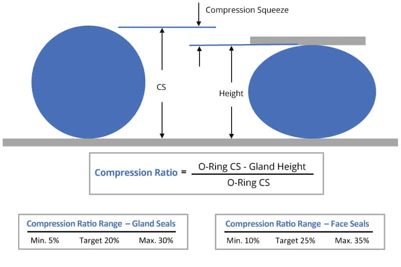
Parker`s ORing Selector is an engineering tool which offers Oring material and size selection combined in one tool Both are interlinked, thus ensuring the best possible combination of the calculated Oring size and material choice The ORing Selector covers both imperial and metric standards How to use Watch our VideoORING REFERENCE AS568 SIZES 1 Oring tolerance stackup) and the smallest possible Oring in the largest possible groove Throughout this reference guide the term "compression" is used for describing what provides the sealing force Since elastomers are essentially incompressible, the technically correct term would be "deformation" Compression is used, as it is the moreThe Oring to roll slightly in its groove under certain conditions of motion, but the rolling action is not necessary for normal operation of the seal The shape of the groove is unimportant as long as it results in proper squeeze of the Oring Groove dimensions are shown in the tables beginning on page 138 The groove depth is measured


Danco O Ring Size Chart Shefalitayal


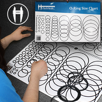
Learn How To Measure O Rings The Right Way O Ring Size Chart
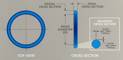
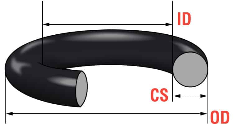
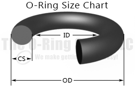
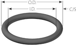
Get a quote for standard or custom sized Orings Need help sizing your hardware for standard sized Orings?Step 3 Choose the correct hardness for your application by going to our rubber hardness chart Step 4 Design and dimension the groove that your Oring will go into by researching our Oring Groove Design guide Step 5 Choose a standard size AS568 Oring using this Oring Size Chart Otherwise contact us and we can custom mold any size orTwo dimensions describe the size of an Oring its inside diameter (ID) and its crosssectional diameter (CS) (see Figure 1) Understanding Oring Sizes and Tolerances Standard Sizes The standard sizes used by Parco and the other major Oring manufacturers in the United States are defined by Aerospace Standard AS568B, Aerospace Size Standard for Orings That document,


Sae J518 O Ring Assortment Kits On Anchor Fluid Power
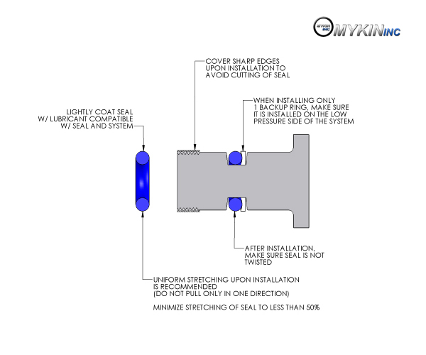


O Ring Installation O Ring Installation Guide Mykin Inc
And 0060" for sizes 8" OD and above measured from true square line COLUMN 3 Gasket seat The pipe surface shall be free from indentations, roll marks, and projections from the end of the pipe to the groove, to provide a leaktight seal for the gasket All loose paint, scale, dirt, chips, grease and rust must be removed It continues to be Victaulic's firstThe ORing Store LLC ORing Groove Chart ORing Cord Stock OSK™ Assorted ORing Kits OSK™ ORing Repair Kits OSK™ Hydraulic Seal Kits OSK™ Air Nailer ORing Kits ORing Lube ORing Tools AS568 ORings (Inch) Metric ORings (mm) OSK Pool, Spa & Pump Orings Hydraulic Seals Inch ORing Glue & Thread Sealant Vulcanized ORings ORing Splice Kits & ToolsThe AS Oring Size Chart has a column that shows the Nominal Size alongside the Actual Size Originally the nominal size was just for a listing of the approximate fractional dimensions of the Oring Prior to the common use of dial calipers many people called out a 1 inch by 11/4 rt = Oring, this was a dash 214 Oring They used to also use these fractional dimensions as the gland size
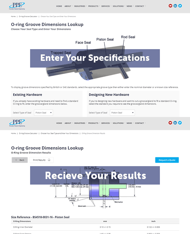


O Ring Groove Dimensions Calculator Precision Polymer Engineering


Sae J1453 O Ring Face Seal Groove Size Chart Knowledge Yuyao Jiayuan Hydraulic Fitting Factory
Common Metric ORings Sizes Tolerances var y by use, please see our tolerance pages Thousands of nonstandard sizes are available in stock or can be made within a few weeks typically without tooling fees so no need to settle for a less than optimal fit Size CS (IN) ID (IN) OD (IN) CS (MM) ID (MM) OD (MM) 05X13 00 0051 0091 050 130 230ORing Reference AS568 Sizes AS568 ORing Size Reference Freudenberg and NOK Group 1 The Simrit ORing Design Quick Reference This design quick reference guide is intended for use in specifying Oring and groove dimensions for static applications with pressures less than 1500 psi The guidelines are for the nominal condition The minimum and maximum conditions should alsoMetric oring groove designs vary greatly and choosing the right one for your application is important for maximum oring performance This metric oring groove design reference guide will help you find the right radius, backup, pressure and other oring dimensions for basic applications Once you find the exact metric oring you need, you can easily order online from the world's largest o
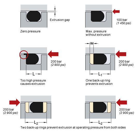


O Rings And Back Up Rings Skf Skf
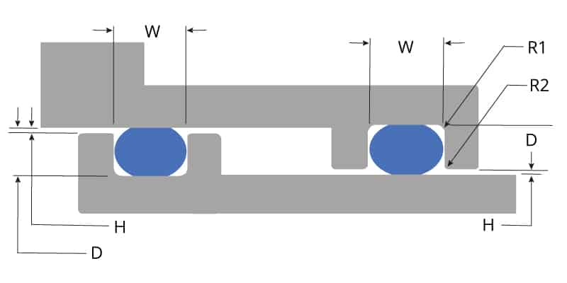


O Ring Groove Design Global O Ring And Seal
BS Specification for metric dimensions of toroidal sealing rings ('O'rings) and their housings Section sizes according to this standard include 16mm, 24mm, 30mm, 41mm, 57mm, 84mm ORing Reference Number According to BS4518 the ORing reference number = ORing Inside dia (mm 4 digits 1 decimal place)"" O Ring Section (mm 2 digits 1 decimal place)


O Ring Groove Design Standard As568b Seal Design Inc


Www Applerubber Com Src Pdf Seal Design Guide Pdf


O Ring Cross Section O Ring Groove Design Data
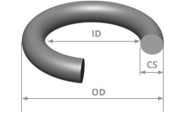


British O Ring Size Chart Bs British Standard O Ring Sizes


How To Use An O Ring In A Non Circular Groove Pattern


O Ring Groove Design Guides Engineering Quick Reference
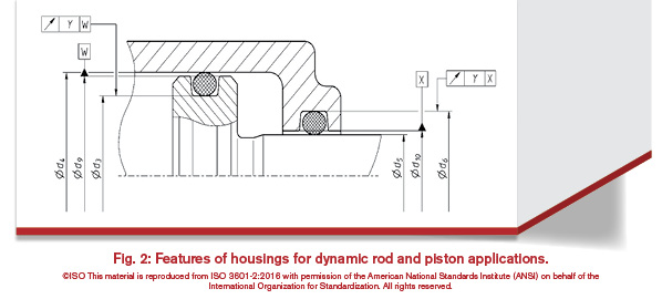


History Of The Iso 3601 Series Of Standards For O Rings Fluid Power Journal


O Ring Groove Design Standard As568b Seal Design Inc


1


Www Hitechseals Com Includes Pdf O Ring Brochure Pdf
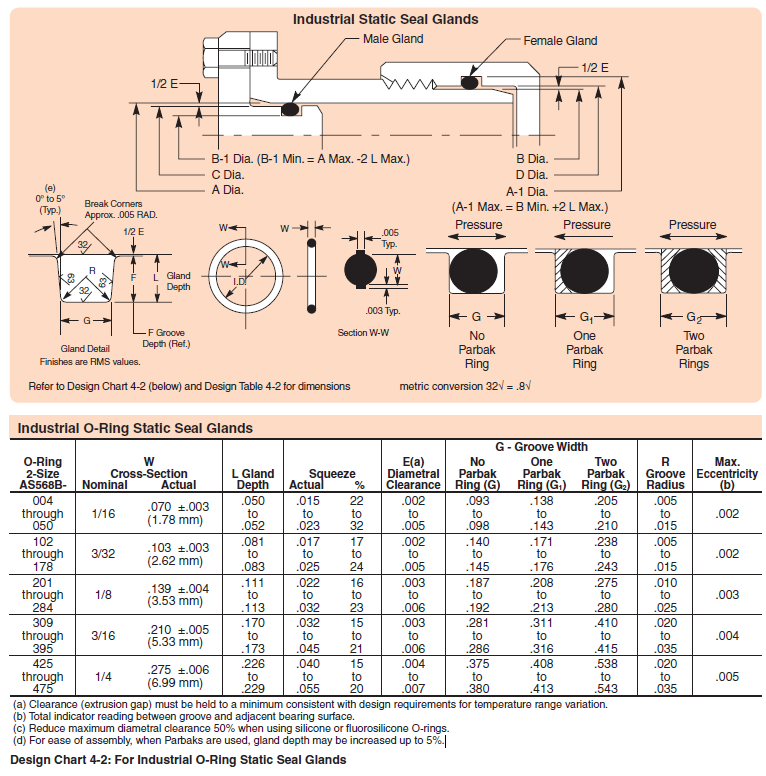


Designing Axial Static O Ring Grooves To Industry Standards Grabcad Tutorials
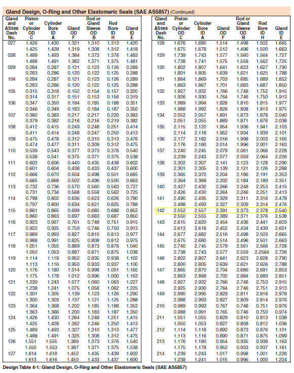


Designing Axial Static O Ring Grooves To Industry Standards Grabcad Tutorials


Engineering


O Rings And Seals Parker Tube Fittings Division Pdf Catalogs Technical Documentation Brochure
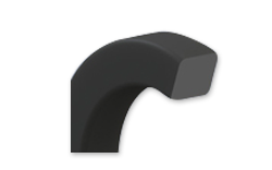


O Ring Size Chart For U S Metric Standard Sizes
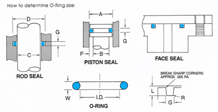


O Ring Groove Design
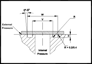


O Ring Seals Roy Mech


O Ring Groove Design Global O Ring And Seal


O Ring Size Chart Pdf Sae O Ring Size Chart


O Ring Calculator Ceetak Sealing Solutions


Www Hitechseals Com Includes Pdf O Ring Brochure Pdf


Http Www Allsealsinc Com Parcoo Ringsizechart Pdf


O Ring Size Chart Rubberpartscatalog Com


Standard Dovetail Grooves Dovetail Groove Engineering Design Guide


O Ring Groove Design Guides Engineering Quick Reference


Accessories Measurement Tools


Untitled Document
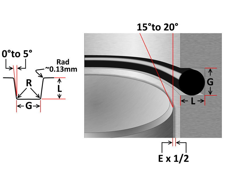


O Ring Groove Design Sealing Australia
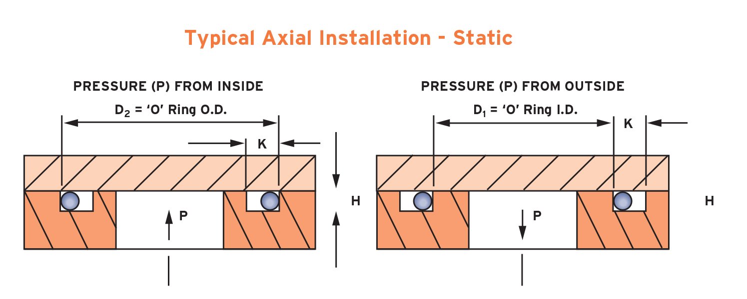


What Is An O Ring Selection Material And Storage Barnwell
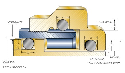


Groove Design O Ring Seals Minnesota Rubber Plastics


Metric O Ring
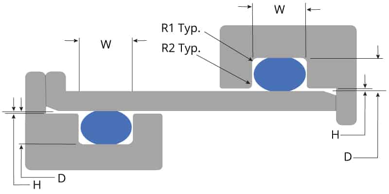


O Ring Groove Design Global O Ring And Seal


Static O Ring Design Chart Marco Rubber Plastics Custom O Rings Supplier


V Ring Seals Seal Design Inc


Great Resource For Designing With O Rings Inventor Tales


Parker O Ring Engineered Seals How To Use The Parker O Ring Handbook Youtube


O Ring Size Charts As568 Metric Global O Ring And Seal


O Ring Groove Design Overview Engineering Guide


Physics Instrument Shop O Rings


O Ring Groove Design Rubber Shop


O Ring Groove Design Daemar Inc


Sae Code 61 O Ring Groove Dimensions Knowledge Yuyao Jiayuan Hydraulic Fitting Factory


Pdf4pro Com Cdn The Seal Man S O Ring Handbook 587f39 Pdf


4000 Series O Ring For Sae J 1926 2 3 Stud Ends Air Way Manufacturing


O Ring Groove Dimensions Pdf Dimensions Ring Joint Facings Asme B16 5 Pressure Class 150


Quad Rings All Seals


O Ring Groove Design Global O Ring And Seal


Newdealseals Com App Uploads 04 Newdealseals O Ring Handbook 14 Pdf


O Ring Grooves


O Rings An Overview Sciencedirect Topics


Sae J518 O Ring Assortment Kits On Anchor Fluid Power


Www Ashtonseals Co Uk Files Mydocs Parker O Ring Handbook Pdf


O Ring Seals Brochure Dowty Seals Dowty Heritage


O Ring Sizes And Dimensions Seal Design Inc


Metric O Ring Dimensional Tolerances


Sae J1453 O Ring Face Seal Groove Size Chart Knowledge Yuyao Jiayuan Hydraulic Fitting Factory


O Ring Groove Design O Ring Groove Dimensions Mykin Inc


Sae Flange O Ring Code 61 Dimension Charts Knowledge Yuyao Jiayuan Hydraulic Fitting Factory


O Ring Static Face Seal Groove Design Guide


Z98 D1xd2 O Rings Redirecting And Seal Cooling System Z Product Catalogue Hasco Portal


The Parker O Ring Selector Easy Fast And Reliable Selection Of O Ring Materials And Sizes In A Single Application


Http Www Allsealsinc Com Parcoo Ringsizechart Pdf


O Ring Size Chart Pdf Sae O Ring Size Chart


Custom Metric O Rings Metric O Ring Seals Standard Metric O Rings


O Ring Size Chart For U S Metric Standard Sizes
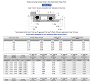


O Ring Groove Design Guides Engineering Quick Reference
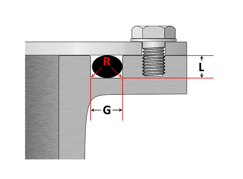


O Ring Groove Design Sealing Australia


O Ring Groove Dimensions Pdf Dimensions Ring Joint Facings Asme B16 5 Pressure Class 150
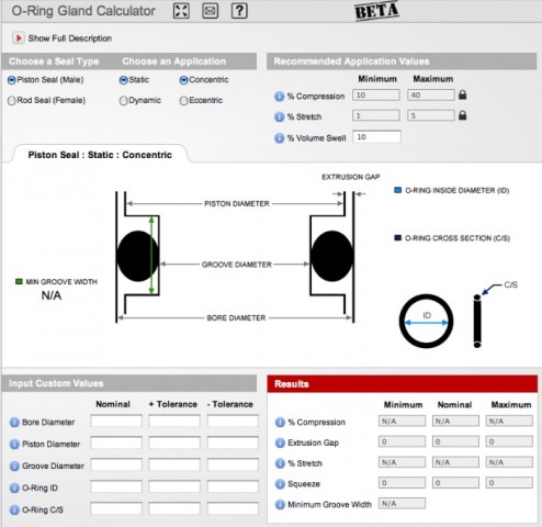


New Gland Calculator Tool At Applerubber Com Official Apple Rubber Blog
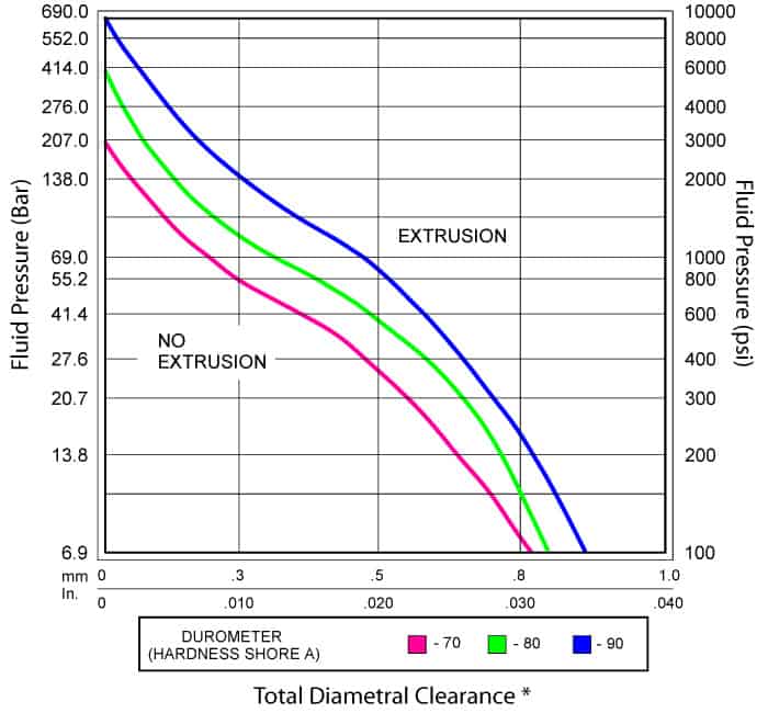


O Ring Groove Design Global O Ring And Seal


Metric O Ring Groove Design Reference Guide
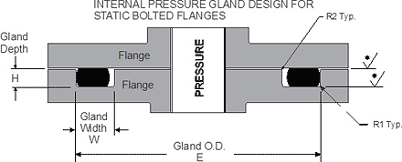


O Ring Static Face Seal Groove Design Guide


O Ring Groove Design Metric Seal Design Inc


Buna O Ring O Ring In Houston And Minneapolis Dichtomatik


0 件のコメント:
コメントを投稿