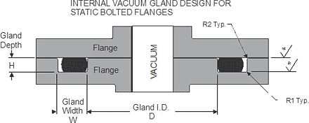
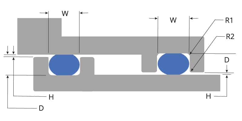
ORing Handbook Parker Hannifin ORing Diision Europe ORing Handbook Parker Hannifin ORing Diision Europe Preamble Sealing technology by ParkerPrädifa The Engineered Materials Group of the Parker Hannifin Corporation is the worldwide leader in the field of designing, developing and manufacturing sealing systems, vibration dampers, EMI shielding systems and heatCall Us Seal & Design Canada Toronto, Ontario (416) Toll Free Headquarters Clarence, NY (716) Higbee Division Syracuse, NY (315) Email Us Seal & Design Canada Toronto, OntarioFor a bore (piston) sealORing Min Groove Diameter = Max Bore Diameter – (2 x Recommended Gland Depth) c For a face sealORing Max Groove Depth = Recommended Gland Depth – Application Clearance With a face seal, if the two surfaces to be sealed are in direct contact (such as with a cover), the seal groove depth is simply the Recommended Gland Depth Groove Width
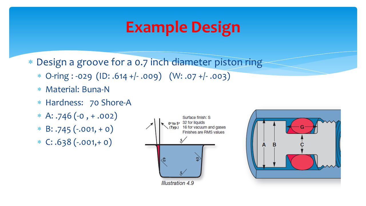
Design Of O Ring Seals Ppt Video Online Download
O-ring piston seal design
O-ring piston seal design-For a highpressure seal to work to optimal levels, oring design and manufacture again depends on choosing specific materials for better performance under specific conditions Orings function on the principle that even pressure placed on the (more or less incompressible) oring material creates predictable deformation patterns around the perimeter of the gasket in its groove This meansIn dynamic seals, such as a piston moving inside a cylinder, the recommended maximum compression is somewhat less at 30% Seal Type Recommended Maximum Compression % C static 40% 040 dynamic 30% 030 Typically, compression is a design input assigned by the design engineer In this case, CS is found by inverting the above compression equation, To
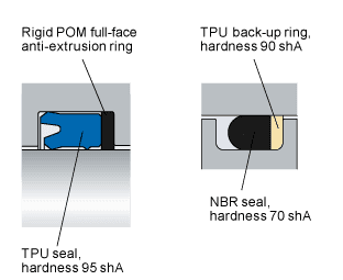


Gap Extrusion Skf Skf
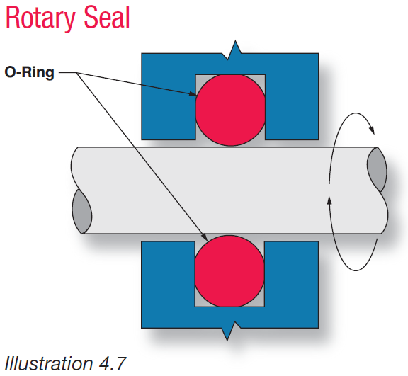
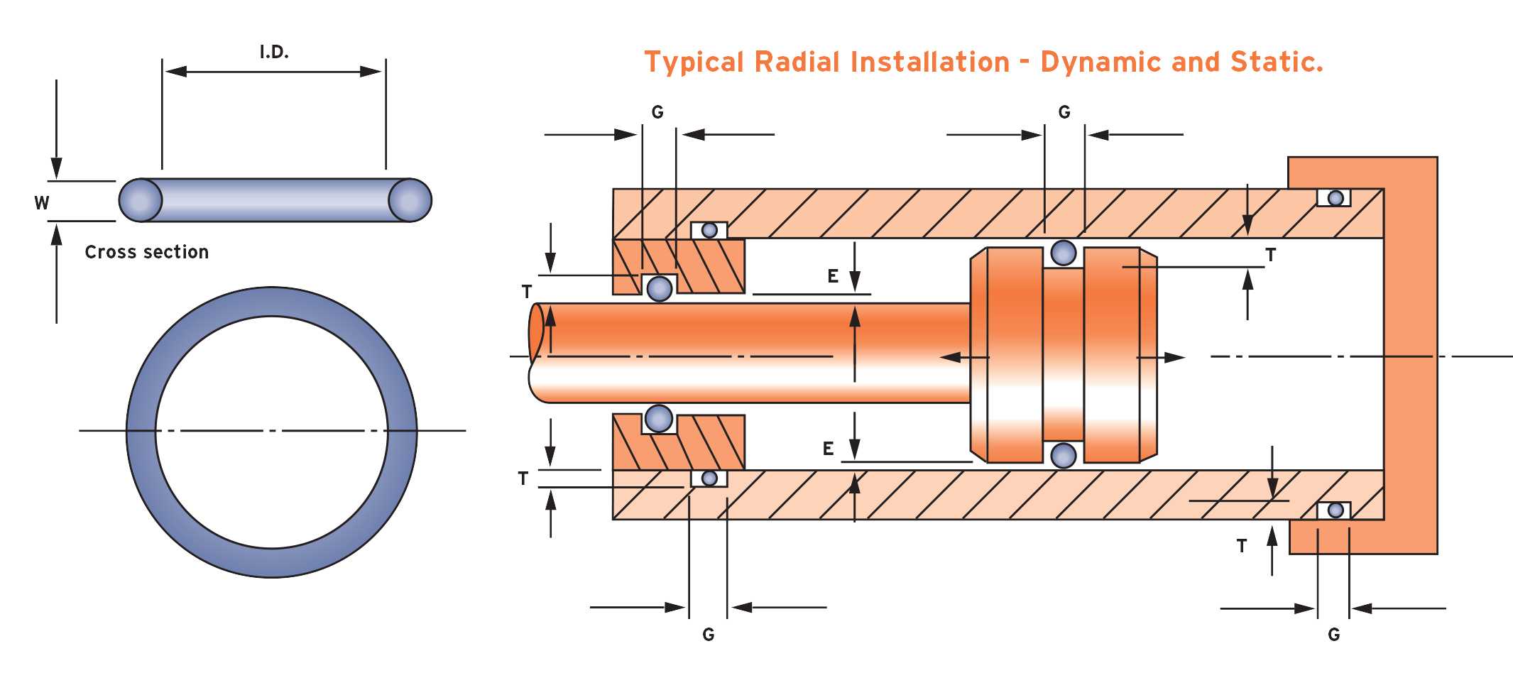
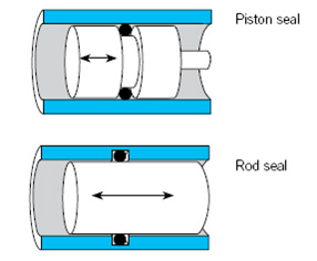
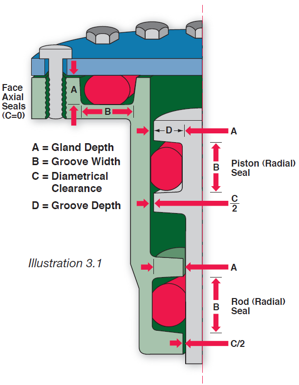
Gland Design 4 11 Major Classifications All Oring seal applications are categorized in terms of relative motion In situations involving little or no motion relative to the seal, the Oring application is STATIC In situations involving reciprocating, rotating, or oscillating motion relative to the seal, the Oring application is DYNAMIC Static Seal Types Static seals are categorized asOf the Oring between the piston and cylinder or shaft and groove, up to 5,000 psi using 90 durometer compound ROTATING SEALS (Design Chart 5) Rotating seals should be limited to shafts having the following maximum rotational speed Shaft Diameter 125 280 – 350 ft/min Shaft Diameter 281 625 – 400 ft/minPiston or rod seal Why an ORing Works As Illustration 31 shows, a properly designed sealing system incorporates some degree of initial Oring compression At atmospheric pressure, only the resiliency of the compressed Oring provides the seal However, as system pressure activates the seal, the Oring is forced to the low pressure side of
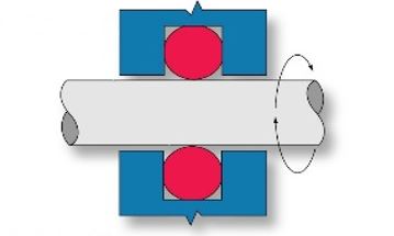
An Oring is a torus, or doughnutshaped ring, generally molded from an elastomer, although Orings are also made from PTFE andThe ERIKS Oring design calculator features the calculation of • oring dimensions for the use in a specific groove • groove dimensions for the use of a specific oring • evaluation of both, any combination of oring and groove for axial seals with inner or outer pressure, piston seals and rod seals Worldwide unique online calculation tool taking into consideration of the thermalReciprocating seals are a dynamic version of either a male radial or female radial Oring design In a reciprocating seal, there is relative reciprocating motion (along the shaft axis) between the inner and outer elements This motion tends to slide or roll the Oring, or sealing surface of the Oring, back and forth with the reciprocal motion Examples of a reciprocating seal would be a
Oring seals This can be prevented by cutting the outer Oring so it cannot seal Since this can easily be forgotten, it is preferable to provide a vent hole between the two Orings It should vent downward so it will not become clogged with dirt The sample problem provided in Table 51 explains how to design the gland for such an Oring wiperThis Oring seal design section will give you step by step instructions on how to design a seal or rubber part for your application Consider this a rubber guide or Oring guide in helping you find the exact rubber material and size you need Some parts of this online rubber or Oring design guide can be downloaded in PDF but everything can just be printed directly from our website for yourThe Oring calculator tool is intended to form the basis of an oring installation, and assist with selection of oring and hardware dimensions Recommendations are based on available technical information, and are offered as suggestions only, any reliance placed on such information by the user is strictly at the user's risk Ceetak recommends that any guidance provided, is reviewed


Sealink Sealing Mechanism Lubricant Free Mechanical Seal Design Sealink


Untitled Document
Oring groove design is a key consideration in the oring selection process Browse design considerations and recommendations for static face seals, metric orings, static dovetail orings, static rodpiston orings and dynamic rodpiston oringsFor pistontype seals the ID of the Oring should be smaller than the gland diameter so that the installed Oring is always slightly stretched, even with the largest possible Oring ID and smallest possible gland diameter For rodtype seals the OD of the Oring should be slightly larger than the glanddiameter so that there is always some interference Maximum = 5% Minimum = 0% Gland Design for Dynamic Seals (ORing and XRing) Machining To minimize premature wear and seal failure, the hardware surfaces which contact the seal during installation and system operation must be properly prepared Preparation consists of appropriate selection of materials, as well as machining for optimum surface finish To prevent seal extrusion or nibbling,


What You Need To Know About Dynamic Seal Applications Hot Topics


Dynamic Seal An Overview Sciencedirect Topics
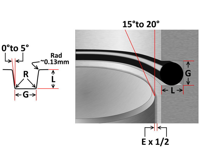
Designing the parts of an application where orings will be applied is broadly termed "oring groove design" In order to seal properly, the oring has to deform in the application by being compressed and stretched in any number of ways The design of the groove where the oring sits plays a major role in how the oring performs its sealing role Extrusion Limits;PTFE composite rotating piston seal, o ring activated Compact design suitable for small installation spaces where a low friction seal is required Wide chemical and thermal resistance depending on o ring material selection Wide range of PTFE compounds Read More RB10A Pressure Max 300 bar Temperature Min 50 °C Max 210 °C Speed Max 04 m/s PTFE composite heavy duty rotating pistonORing Groove design plays an important part in how an oring seals Learn More > Contact World Class;
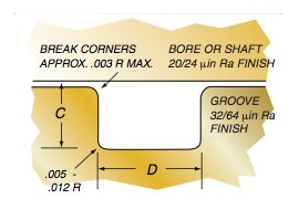


Groove Design Quad Ring Seals Minnesota Rubber Plastics


O Ring Design Cad Tutorial Zdspb Tech
One general guideline for good Oring application and design is to maintain a range of % sqeeze on the Oring (~1040% for static and no more than 30% for dynamic) No less than 75% of the seal crosssection should be contained within the groove to ensure the seal does not "roll" or extrude out of the grooveThe oring seal design process begins with understanding the gland type in which the seal will be seated To ensure the oring fits properly it is recommended that the oring is stretched 1 to 5% circumferential, with ideal stretch at 2%Be it dynamic or static operation, radial or axial loading, vacuum or high pressure The following information is a guide for o'ring
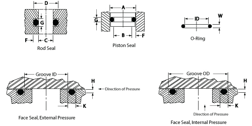


O Ring Groove Design Daemar Inc


Dynamic Reciprocating Gland Design Dynamic O Ring Gland
Kefloy SlipRing® Type 2522 Is a double acting piston seal consisting of an outer sliding part of Kefloy® energized by a rubber ORing SlipRing® is pressure responsive SlipRing® can be used with a great variety of fluidsO'ring Groove Design As important as the o'ring seal itself is the groove that the o'ring seats into The groove must be designed to accommodate not just the o'ring size, but also its intended usage;Depending on your application you can have the groove be cut in either the piston or the bore The groove
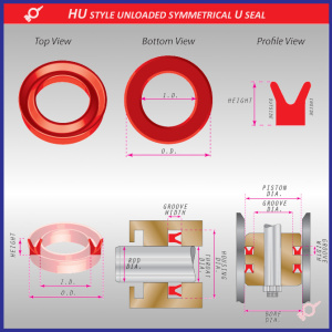


What Are U Cups U Seals Polypaks Rocket Seals Inc


Http Practicalmaintenance Net Wp Content Uploads Working Design Considerations And Maintenance Of O Rings Pdf
Call Us Seal & Design Canada Toronto, Ontario (416) Toll Free Headquarters Clarence, NY (716) Higbee Division Syracuse, NY (315) Email Us Seal & Design Canada Toronto, Ontario If the good piston seals catalogue design only increases the pressure unilaterally, it will not cause the oring seal The root cause of the damage is due to the permanent deformation of the oring under the high temperature And high pressure of the working environment and the bite caused by being squeezed into the gap There are several reasons for the permanent deformation of piston sealsThese designs require considerable installation stretch If assembly breakage is incurred, use a compound having higher elongation or use a twopiece piston Design Table 42 Gland Dimensions for Industrial ORing Static Seals, 1035 Bar (1500 psi) Max Gland Dimensions for Industrial ORing Static Seals, 1035 Bar (1500 psi) Max† (Continued)
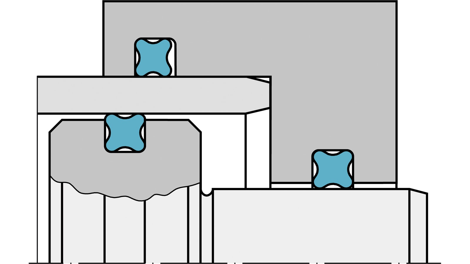


Quad Ring Seals X Ring Static Seals Trelleborg


What You Need To Know About Dynamic Seal Applications Hot Topics
ORing Groove design plays an important part in how an oring seals Learn More > Contact World Class;Those who are already familiar with Oring seal design may simply refer to the appropriate design tables for the information needed Even those who have designed many Oring seals may profi t by reviewing the basics from time to time 11 What is an ORing?Call Us Seal & Design Canada Toronto, Ontario (416) Toll Free Headquarters Clarence, NY (716) Higbee Division Syracuse, NY (315) Email Us Seal & Design Canada Toronto, Ontario


A Simple Guide To Radial Seals Sealing Fundamentals Parker Hannifin


Back Up Rings O Rings Performance Sealing Inc
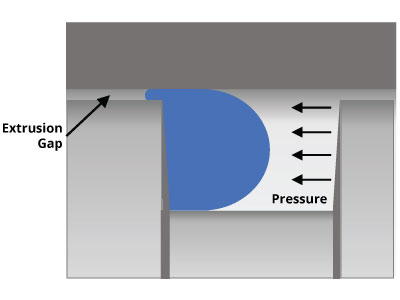
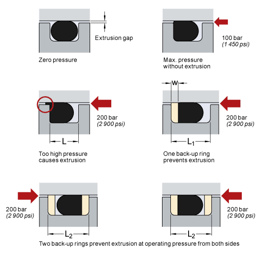
Seal & Design Established in 19 by Dean T Penman, Seal & Design Inc has established itself as an industry leader in the sealing and gasketing industry Seal & Design is a leading manufacturer and distributor of die cut gaskets, seals, orings, and molded rubber products Dean's original philosophy included exceeding customer expectationsFor pistontype seals the ID of the Oring should be smaller than the gland diameter so that the installed Oring is always slightly stretched, even with the largest possible Oring ID and smallest possible gland diameter For rodtype seals the OD of the Oring should be slightly larger than the gland diameter so that there is always some interference Maximum = 5% Minimum = 0% The biggest weakness of radial Oring seals is that the clearance between components creates a path for the Oring to extrude due to the pressure acting on it Components called backup rings can help alleviate this Backup rings are designed to spring out of the gland and block the extrusion gap Where an Oring alone could withstand perhaps only 00 psi, a backup


Buna O Ring O Ring In Houston And Minneapolis Dichtomatik
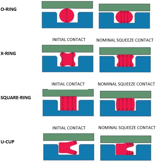


What You Need To Know About Dynamic Seal Applications Hot Topics
The KB21 profile is a symmetrical sharplipped ORing energised UCup seal and is commonly used in the hydraulic repair market as it can function in both rod and piston applications The ORing energiser in this seal provides further sealing force across the sealing lips to ensure leak free performance even Read More KB21Q Pressure Max 400 bar Temperature Min 55 °C MaxRubber Seals, Sealing Devices & ORing Seal Design AppleDesign Chart 53 provides the basis for calculating gland dimensions for a floating pneumatic Oring design Standard Oring sizes have the dimensions calculated and are listed in table 53 To use the table, start with the diameter of either the bore/cylinder or the piston


1
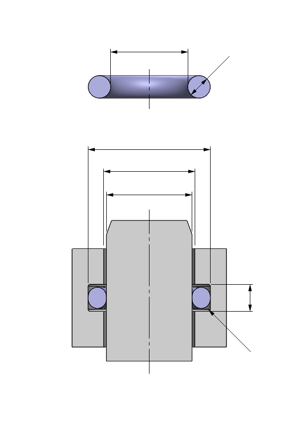


O Ring Calculator Ceetak Sealing Solutions
Learn more about static oring groove design for rod, cylinder, and piston orings from Marco Rubber, the industry leader in standard and custom orings Welcome to the world's largest database of specialty and standard sealing productsDesign Chart 52 provides a reasonable basis for calculating reciprocatingOring seal glands Design Table 52, which followsit, contains recommendedgland dimensions for the standard AS568A Oring sizes The major difference from the military gland dimensions (Design Table 51) is the use of standard cylinder bore and standard rod dimensionsThe SB07 profile is a symmetrical lipped ORing energised UCup seal and is commonly used in the hydraulic repair market as it can function in both rod and piston applications The ORing energiser in this seal provides further sealing force across the sealing lips to ensure leak free performance even Read More


O Rings O Yeah How To Select Design And Install O Ring Seals Tarkka
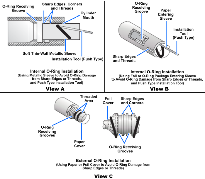


Sealing Devices And Materials Engineering Library
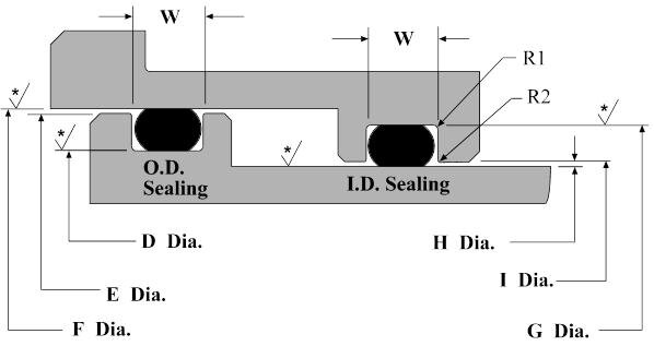
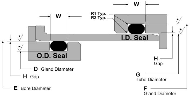
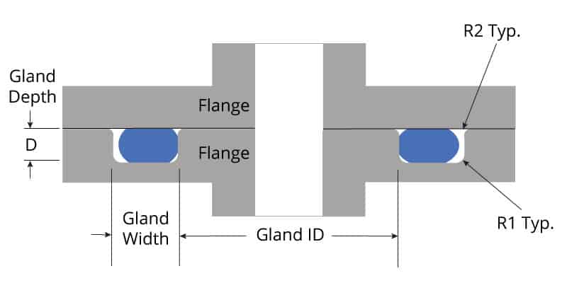
ORing Groove design plays an important part in how an oring seals Learn More > Contact World Class;Oring Gland Design Dynamic Applications There are three types of dynamic applications • Reciprocating Seal • Oscillating Seal • Rotating Seal Application in reciprocating and oscillating motions Groove dimensions for reciprocating and oscillating applications are the same Dynamic applications, due to the motion against the Oring, are more complicated than static applicationsThe oring gland design is more complex for radial seals and requires both the piston and the bore to have precise geometry The bore and the piston have to be concentric to one another One of the faces will be completely smooth and one will have an oring groove cut into it;


China Standard Or Nonstandard Ptfe Piston Seals With Professional Design China Piston Seals Hydraulic Seals
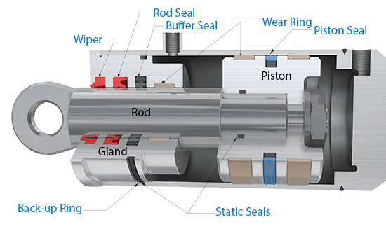


Fluid Seals Hydraulic Seals Hydraulic Cylinder Seals Ahp Seals
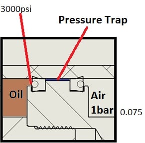
Piston Seals or Piston Rings are used in hydraulic cylinders for fluid sealing They are internal to the cylinder head and seal against the cylinder bore, preventing fluid from flowing across the cylinder head This allows pressure build up on one side of the pistonO ring piston seal design, Wholesale Various High Quality o ring piston seal design Products from Global Sodium Tripolyphosphate Suppliers and o ring piston seal designA piston design where two singleacting seals on the piston for a doubleacting cylinder are used can easily give rise to a breakdown The reason is that a very high pressure can be trapped between the seals Piston seals, both single and doubleacting, can be designed for and used with integrated or separate backup rings and guide rings
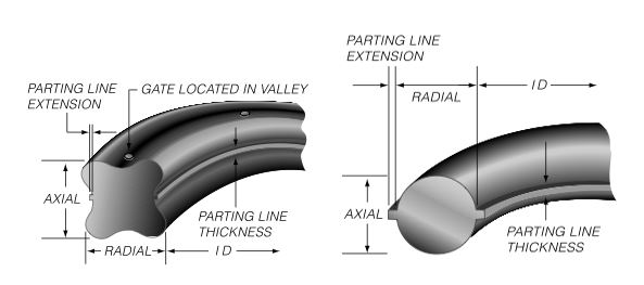


Advantages Of A Quad Ring Over An O Ring


Piston Seals Hydraulic Seals Uk Seals Polymers Ltd
ERIKS standard ORings and load them also into your created design info chemical volume swell (%) cross section diameter (mm) ISO 3601 free Calculate Results Reset calculator42 Static Male and Female ORing Seal Design Design Chart 42 and its accompanying Design Table 42 give one set of dimensions for static Oring seals when the confi guration is similar to a piston or rod application with no motion involved Aerospace Design Standard AS5857 is shown in Design Chart 41 and Design Table 41 for aerospace and military applications For applicationsTry our new Online Oring Store Standard and Metric Sizes Thousands of materials Find Orings by size, temperature range, material type, compliance, and more Find and Buy Marco Orings Online * Recommended surface finish 16 Ra max for gases and 32 Ra max for fluids All dynamic applications to have 16 Ra max


Hydraulic Sealing Solutions Improving Performance Uk Seals Polymers Ltd


Purpose Of The Piston Seal Youtube
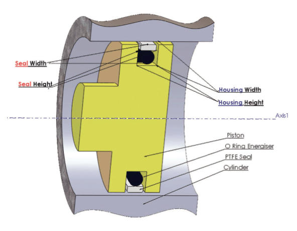
PTFE composite rotating piston seal, o ring activated Compact design suitable for small installation spaces where a low friction seal is required Wide chemical and thermal resistance depending on o ring material selection Wide range of PTFE compounds Read More RB13 Pressure Max 600 bar Temperature Min 50 °C Max 210 °C Speed Max m/s The simple ORing is oneDETERMINING ORING CROSS SECTION Piston Seal 2 3 4, GROOVE ECCENTRICITY 003 øl 248OOO/002 PISTON OD 1 010/ooo GROOVE WIDTH ø /—ooo CYLINDER BORE ø 1008ooo/—002 GROOVE DIA 001" 001 " 001" 001" 0015" 0055" 022" 146" 139" Quantify all factors that can reduce nominal squeeze on ORing cross section, —Y Maximum nominal pistonHighPressure BiDirectional Hydraulic Piston Seal Oringenergized cap seal design The specially designed hard wearing, 60 shore D, selflubricated polyurethane cap is much easier to install than PTFE cap seals and provides high extrusion resistance Further, the design provides a fluid reservoir between the two beveled sealing lips which retains system fluid, resulting in
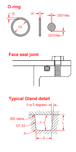


O Ring Wikipedia


O Ring Groove Design Global O Ring And Seal
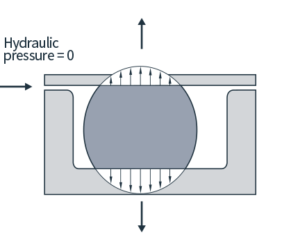
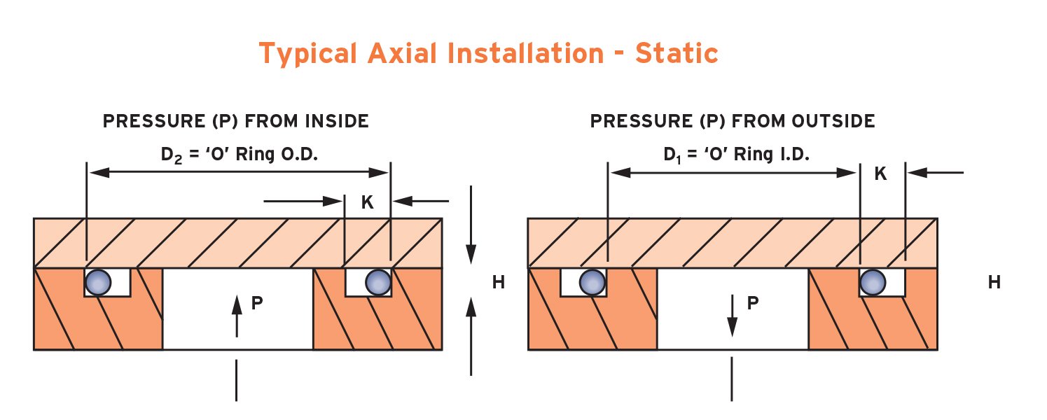
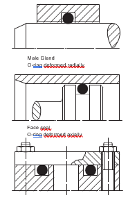
Radial seals and face seals (also known as axial seals) differ from each other in the direction which compression or squeeze is applied to the seal cross sections Radial seals have compression applied to their outside diameter (OD) and inside diameter (ID), as illustrated in Figure 1 below Face seals on the other hand have squeeze applied to the top and bottom of the seal


Basic Knowledge Sealing Business Air Water Mach Inc


O Ring Lusida Rubber Products


Oring Ehandbook


Seal Solutions Guide


Reciprocating Lip Seals Springerlink


What Is An O Ring Selection Material And Storage Barnwell


Gap Extrusion Skf Skf


Hydraulic Cylinder Seal Configuration Back To Back Leaks Fluid Power Engineering Eng Tips


What You Need To Know About Dynamic Seal Applications Hot Topics


O Rings O Yeah How To Select Design And Install O Ring Seals Tarkka


Http Practicalmaintenance Net Wp Content Uploads Working Design Considerations And Maintenance Of O Rings Pdf


When It Comes To Seals And O Rings Martin S Rubber Are Flexible Process Industry Forum


1


Shaft Seals For Rotating Shafts


Fundamental Of O Ring


2 Design And Detail Information O Rings Stock O Ring Webshop


Seals Eastern O Ring Piston Seal Design Guideline


Dynamic O Ring Design Chart Marco Rubber Plastics Custom O Rings Supplier


O Ring Groove Design Sealing Australia


What Is An O Ring Selection Material And Storage Barnwell


Mapa Piston Seal Assemblies Hercules For O Rings Hydraulic Seals Cylinders


O Ring Groove Design Seal Design Inc


O Rings O Yeah How To Select Design And Install O Ring Seals Tarkka


Static O Ring Groove Design A Rod And Piston Glands


Design Of Oring Seals Design Of Oring Seals


O Ring Groove Design Global O Ring And Seal


Mating Ring An Overview Sciencedirect Topics


Fep O Rings Trelleborg Sealing Solutions
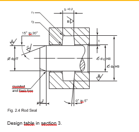


2 Design And Detail Information O Rings Stock O Ring Webshop


The Assembly Of The O Rings Equipment For The Assembly Of The O Rings Elastotech S R L
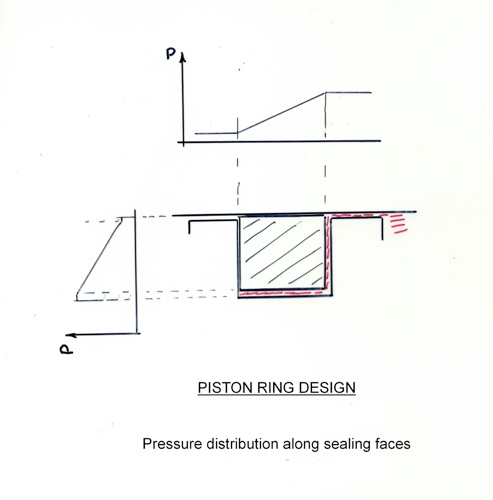


Steam Piston Rings
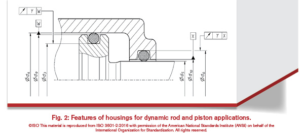


History Of The Iso 3601 Series Of Standards For O Rings Fluid Power Journal
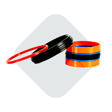


Double Acting Piston Seals Hydraulic Cylinder Piston Seals Hallite


Static O Ring Face Seal Groove Design Guide


O Ring Gland Design Guide Oringstore Com


Types Of O Ring Applications


Design Of O Ring Seals Ppt Video Online Download


Design Of Oring Seals Design Of Oring Seals


Busak Shamban Piston Seals Turcon Aq Seal


Newdealseals Com App Uploads 04 Newdealseals O Ring Handbook 14 Pdf


O Ring Groove Design Global O Ring And Seal


Seals And Sealing Technology Hydraulics Pneumatics
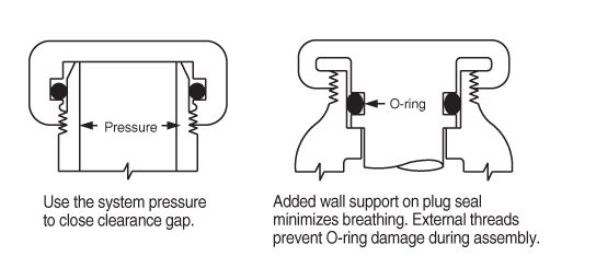


What Are Static Seals Hot Topics


Sealcalc


Enhancement Of Seal Life Through Carbon Composite Back Up Rings Under Shock Loading Conditions In Defence Applications Sciencedirect
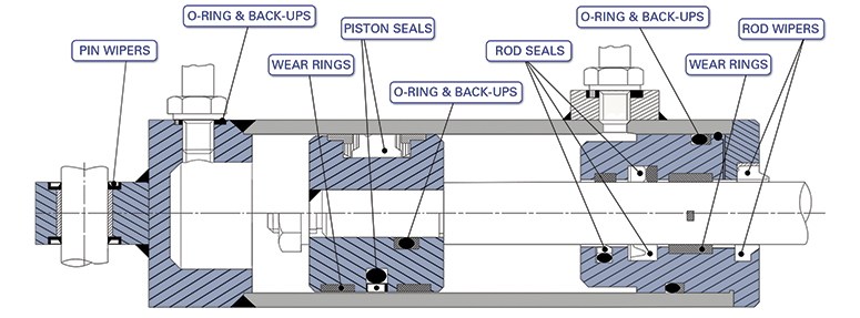


Hydrapak Seals Products O Rings Size Dimensions
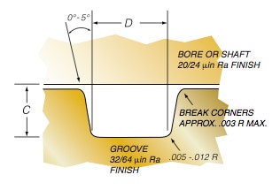


Groove Design O Ring Seals Minnesota Rubber Plastics
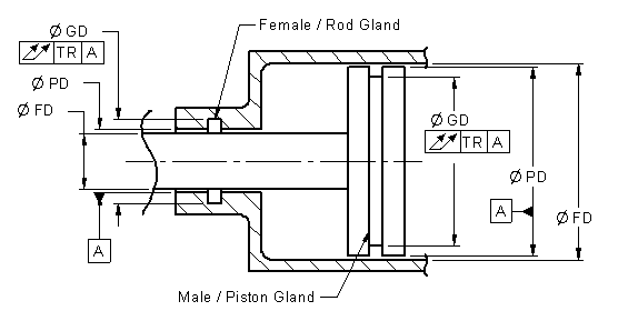


O Ring Installation Design And Specification For Dynamic Applications Engineers Edge


O Ring Seal Gd1000k Series Hunger Profiled Nbr Ptfe


Quad Rings All Seals


Seals


Xu S Sealing Theory And Rectangular O Shaped Ring Seals Science Publishing Group


Fundamental Of O Ring


O Rings And Back Up Rings Skf Skf


O Ring Groove Design Standard As568b Seal Design Inc


Kumar Rubber Store


Seal Design O Ring Design O Ring Design Guide


Would Slippery O Rings Or Seals Improve Your Product Performance


How To Properly Choose Commercially Available O Ring Cross Sections Performance Seals Inc


Hydraulic Seals All Seals


Spring Energized Seals Teflon Ptfe Seal Groove Design Guide


T Seals From Precision Polymer Engineering


Xu S Sealing Theory And Rectangular O Shaped Ring Seals Science Publishing Group


1


How Buffer Rod Seals Influence Rod Seal Performance Hydraulics Pneumatics


Seal Solutions Guide


Seal Design O Ring Design O Ring Design Guide


Oring Ehandbook


1
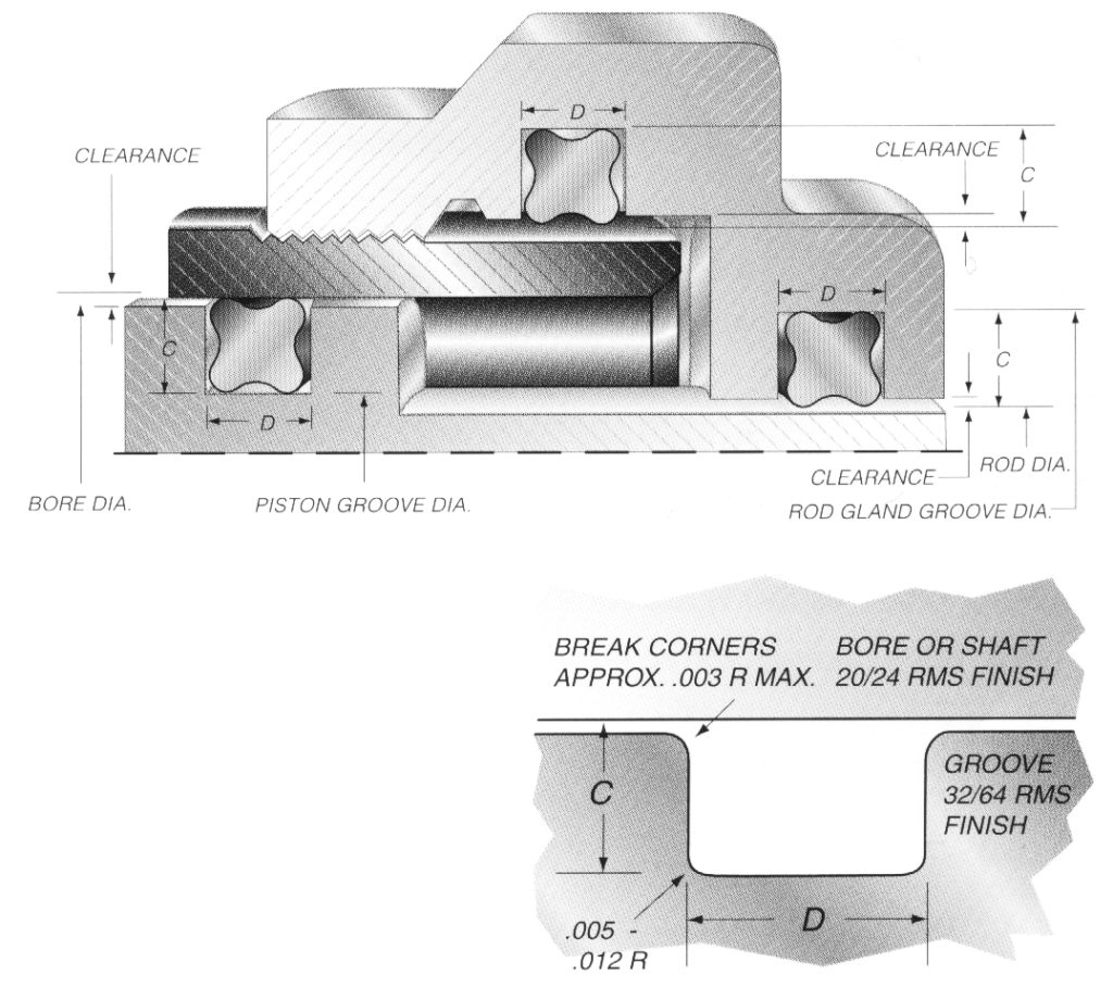


Quad Ring Groove Design Daemar Inc
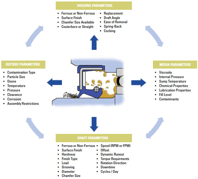


Dynamic Seals Selection Guide Types Features Applications Engineering360
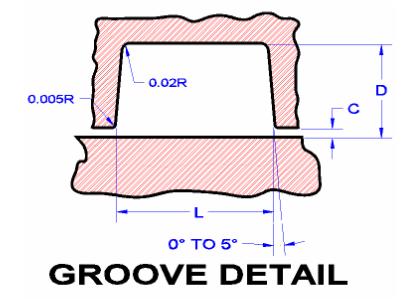


Seals Eastern O Ring Piston Seal Design Guideline
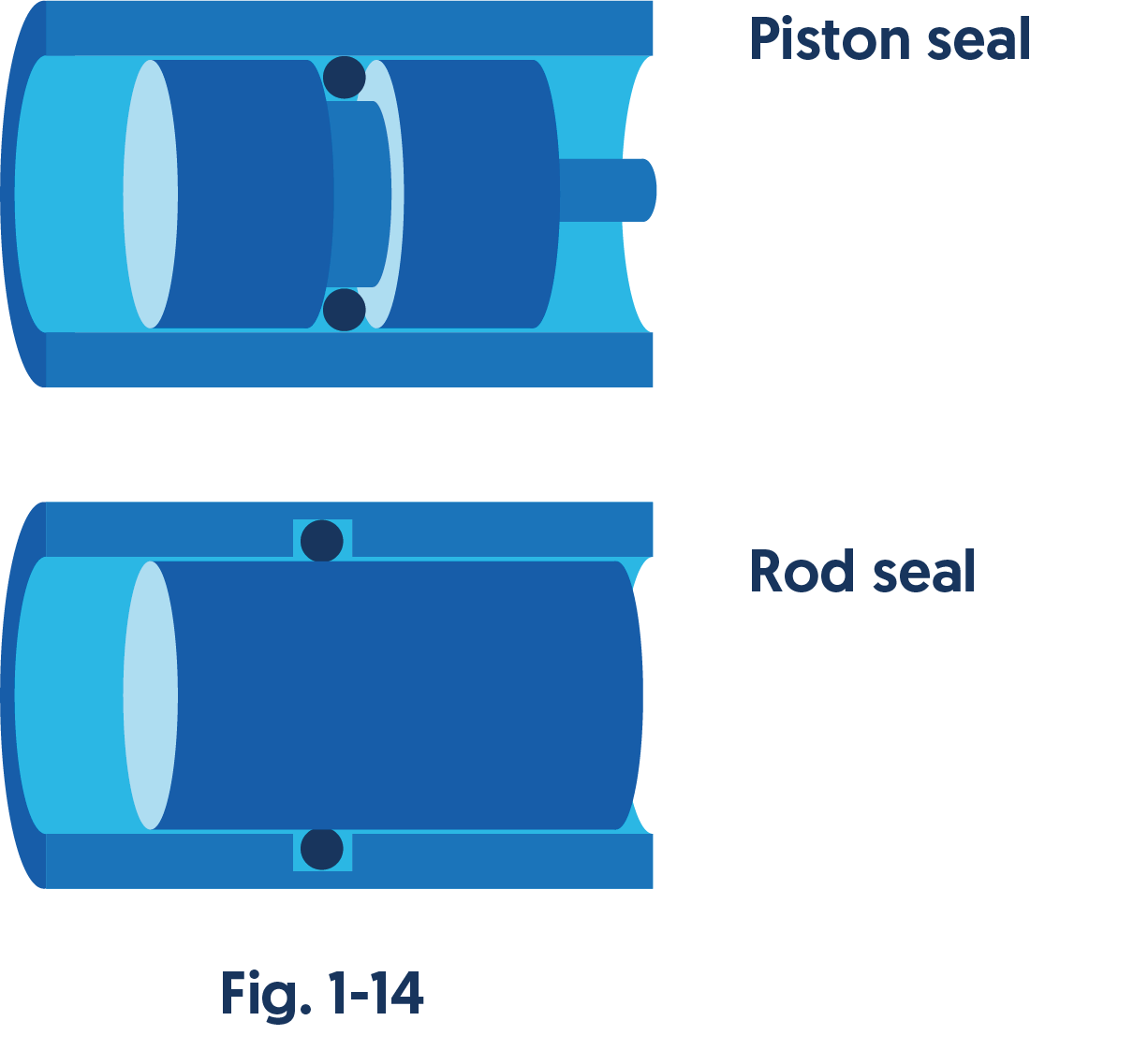


Engineering Basics Guide To O Rings Eriks Shop Nl


The Function Of Hydraulic Cylinder Seals Custom Hydraulics Design
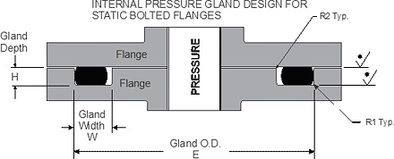


Static O Ring Face Seal Groove Design Guide
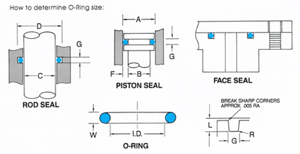


O Ring Groove Design


0 件のコメント:
コメントを投稿